It is important to identify the Load Bearing Walls on which the roof trusses will be supported (in the following plan view drawings all load bearing walls are shown shaded).
The Roof Lines – ridgelines, hip lines, valley lines, gable and eaves overhang lines – at the ends of building sections and at junctions, provide information regarding the required shape of the roof.
In the two examples shown below the wall plans are identical (apart from the parapet wall in Roof B), yet the two roof shapes are quite different, as indicated by the roof lines on the plan drawings.
Roof A
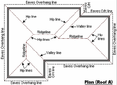
A ridgeline marks the apex of each of the three roof sections on this roof plan. Diagonal lines in the outside corners of the building indicate hip ends. The two partial hip lines in the central section connect the higher ridgeline to the two lower ridgelines on either side of it.The diagonal lines in the two inside corners of the building are valley lines formed where two sections intersect.
Roof B

A ridgeline marks the apex of each of the three roof sections. Gable ends are identified by theridgeline extending over the end wall to the gable overhang line. At a parapet end (at lower left), the ridgeline and roof end at the inside edge of the parapet wall, which extends above the roof.
The parapet and gable walls are not load bearing. The vertical ridgeline meets the left horizontal ridgeline at a point, indicating that these two ridge-lines are at the same height.
This means that the narrower section must have a steeper pitch than the wider section in order to reach the same ridge height. The difference between the pitches of the two sections is also clear from the fact that the hip and valley lines across the corner are not at
45o to the walls and ridgeline.
The following Plan Views of Roof A and Roof B show the building End Types and Junction
Types of these two different roof shapes.
The hatching on these drawings runs horizontally along each roof plane.
Roof A

The bottom left section starts with a hip at the bottom and ends in a valley, which sits on top of the side plane of the top section, forming a Valley junction. The top left section has a hip at both ends, while the top right section has a valley at the left and a hip at the right end. At the junction of the two parallel sections the valley end of the narrower section sits on top of the hip end of the wider section.
Note: In both junctions the second valley line coincides with the lower portion of a hip line, but these lines are not shown because the roof planes on that side of the junctions are continuous across the junctions.
Roof B

At the bottom end of the building the roof ends at the inside face of the parapet wall. At the right end of the building the roof extends over the gable wall. At the under-gable junction the narrower section of the roof is lower and extends to the partial gable wall, while the roof of the wider section is higher and extends to a gable overhang above the lower roof – on one side only. On the other side of this under-gable junction the roof plane is continuous.
Note: Since the pitch differs on either side of the corner, this corner junction will require a customized hip and valley set. Alternatively, a Hip-Valley junction may be used – see Hip-Valley.