In addition to Plan and Elevation views, architects’ drawings may also include Sections.
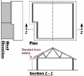
A Section is a “slice” through a building, showing the internal features of the building. The position of this “slice” is indicated on the roof plan by dotted lines, as shown here. The arrows through the dotted lines indicate the direction in which the section is viewed.
Note: A Fink type truss is shown here. The truss type selected in a specific roof depends on the span, pitch and roof cover, as well as on an understanding of structural roof design.
Web configurations included on an architect’s section drawings may usually be ignored.
Section drawings are useful in illustrating the profiles of non-standard trusses, such as on cantilevered or stubbed sections of a building, as shown below.
 A Section through a cantilevered area |
 A Section through a stubbed area |
| Note:Cantilevered and Stubbed areas of a building can be identified on a plan by the position of the overhang line – at a cantilever the overhang line is flush with that of the standard building section, while at a stub the overhang line is stepped in with the stub wall, as shown on the plan drawings above. Cantilevered and Stubbed areas of a building can be identified on elevation drawings by the height of the overhang line – the overhang line maintains the standard height along a cantilever wall, while it is higher along a stub wall, as shown on the West Elevations in the drawings above. | |