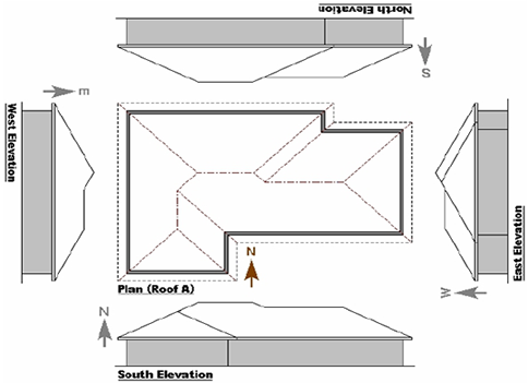
Roof Truss Elevations drawings are side views of a building, named for the direction from which the building is viewed:
The South Elevation shows the south side of the building, viewed from the south looking north;
The East Elevation shows the east side of the building, viewed from the east looking west;
The North Elevation shows the north side of the building, viewed from the north looking south;
The West Elevation shows the west side of the building, viewed from the west looking east;
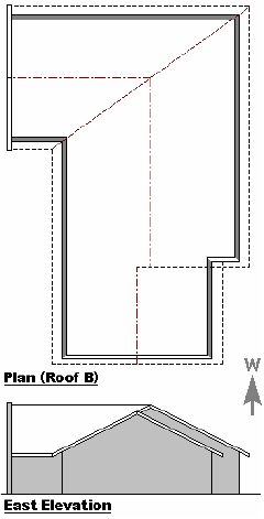
In the drawings of Roof A below, and Roof B on the following page, the elevations are shown rotated around the plan drawing, so that each elevation is positioned on that side of the plan which it depicts.
This is normally done on architectural drawings, but is done here so that the position of hip or valley apexes, wall lines or overhang lines in the elevations may easily be checked by simply laying a ruler or other straight edge across from the plans to the elevation drawings.
The four elevations of Roof A and Roof B are shown again on the following pages, this time with the elevations in the upper right position and, except for the south elevations, the plans have been rotated. In each drawing the elevation depicts the side of the plan which is shown directly above it.
Again, this allows the position of lines or points in the elevations to be checked by laying a straight edge across from the plans to the elevation drawings.
The horizontal roof lines in this elevation correspond with the horizontal ridgelines on the plan. The apex of the hip at the left of the elevation corresponds with the vertical ridgeline on the plan.
The sloping roof lines from the highest section of the roof elevation connect this higher roof in the centre to the lower roofs on either side, corresponding with the partial hip lines in the plan.
South Elevation
The South Elevation shows the south side of the building, viewed from the south looking north.
The horizontal roof lines in this elevation correspond with the horizontal ridgelines on the plan.The apex of the parapet wall on the left of the elevation corresponds with the vertical ridgeline on the plan.The height of the central section extends from the apex of the left section in the elevation, where the roof is obscured by the parapet wall, to the under-gable junction.
Note the change in height of the roof at this junction, with a continuous roof plane extending across the front of the two sections on the right of this elevation.
East Elevation
The East Elevation shows the east side of the building, viewed from the east looking west. The roof plans have been rotated through 90o (clockwise), so that the view illustrated by the elevation reflects the lower side of the plan drawing above it.
The hip end of the central section of the roof plan is visible in the elevation drawing behind the front hip end. The two vertical ridgelines on this plan drawing correspond with the apexes of these two hips in the elevation. The horizontal roof line at the left of the elevation drawing extends from the apex of the hip at the left to the apex of the valley at the side of the higher hip end, corresponding with the horizontal ridgeline at the top of the plan drawing.
The partial gable wall at the under- gable junction is visible behind the front gable wall in the elevation. The two vertical ridgelines on this plan drawing correspond with the apexes of these two gable walls in the elevation. The horizontal roof line in this elevation drawing extends from the parapet wall on the left to the apex of the higher roof section on the right,
corresponding with the horizontal ridgeline in the plan drawing.
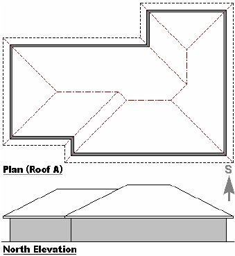
North Elevation
The North Elevation shows the north side of the building, viewed from the north looking south.
The roof plans have been rotated through another 90o (a total of 180o relative to the original orientation).
Again the view illustrated by the elevation reflects the lower side of the rotated plan drawing above it.
The horizontal roof lines at the top of each roof section in this elevation correspond with the
horizontal ridgelines on the plan. The section at the top right of the roof plan is not visible in the elevation drawing, as it is obscured by the higher central section of the roof.
The horizontal roof lines in this elevation correspond with the horizontal ridgelines on the plan. The right hand horizontal ridgeline on the plan extends from the overhang line at the under-gable junction to the vertical ridgeline on the right, corresponding with the horizontal roof line of the higher roof in the elevation drawing. Note the change in height of the roof at the Under-gable junction, with a break in the roof planes across the two sections of the building shown in this view. At the right of the elevation the parapet wall is visible above the sloping roof.
West Elevation
The West Elevation shows the west side of the building, viewed from the west looking east.The roof plans have been rotated a total of 270o relative to the original orientation.
The lower vertical ridgeline on this plan corresponds with the hip apex of the left section of the roof in the elevation drawing. The horizontal ridgeline on the plan extends from the apex of the valley at the side of the hip end to the apex of the hip end at the right, corresponding with the horizontal roof line in the elevation drawing.
The lower vertical ridgeline on this plan drawing corresponds with the apex of the sloping end of the roof in the elevation drawing.The horizontal ridgeline on the planextends from the vertical ridgeline to the parapet wall on the right,Corresponding with the horizontal roof line in the elevation drawing.


